


You are here:
Crack Repair - Permanently Repairing Cracks in Industrial Floors
Quantec Industrieböden® GmbH handles crack repair in industrial, logistics, and commercial floors—from fine cracks to structural damage—using a systematic selection process and ensuring predictable approval during operations.
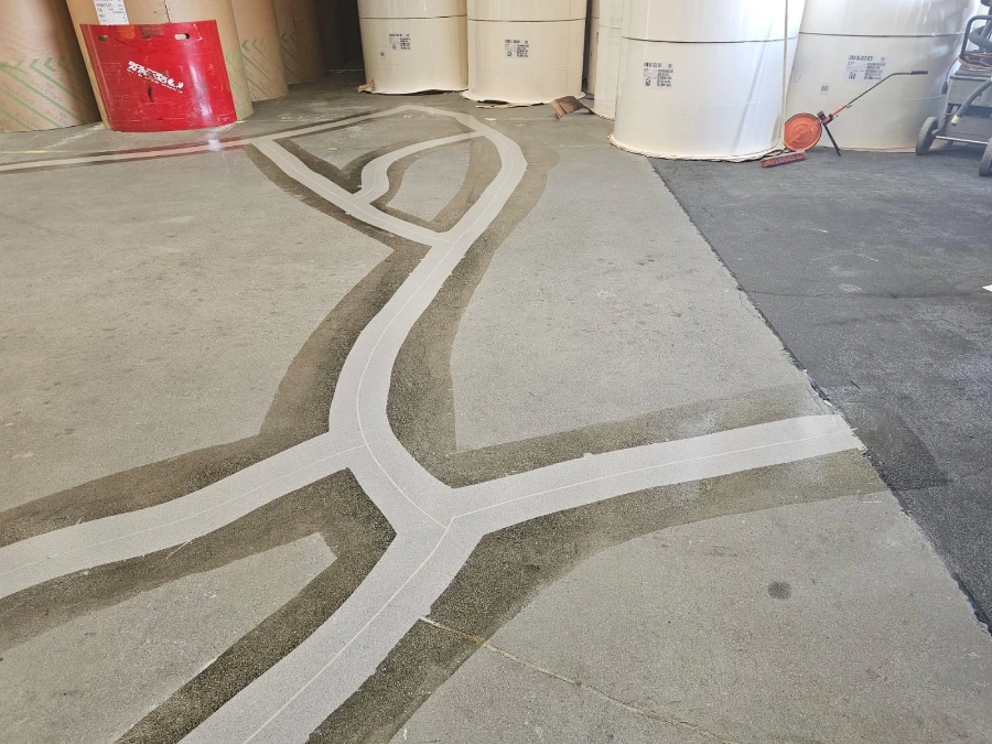
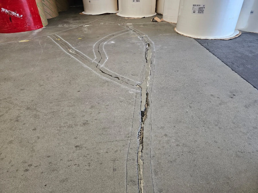
Cracks are rarely “just cosmetic”: In traffic lanes, they become spalling edges; in peripheral areas, they lead to secondary damage; and at transitions, they become recurring repair points. Professional crack repair stabilizes the pavement, reduces edge spalling, and protects underlying layers. The key factor is whether the crack is low-movement, active, or already functioning as a joint.
Why Quantec?
Your Partner for Durable Industrial Floor Renovation
Every crack requires a customized solution. Thanks to our many years of experience, we select the appropriate repair system for every type of damage—ranging from injection resins and special crack-filling materials to high-strength specialty mortars with defined elasticity that accommodate ground movements and reduce the risk of new cracks forming.
This is how we create durable and cost-effective repair solutions for your cracks.
This is how we create durable and cost-effective repair solutions for your cracks.

Properly Assessing Types of Cracks
An approach based on usage, location, and movement patterns rather than a one-size-fits-all solution.
Reduce Consequential Damage
Stabilization of driving lanes, shoulder areas, and transitions.
Scheduled Closure Times
Implementation in phases, in line with the operational logic.
100% in-house work
Our own machinery—no subcontractors.
Why Cracks in Industrial Floors Often Escalate
A crack is an entry point for mechanical damage: rolling loads and shear forces “act” on the edge, dirt particles have an abrasive effect, and a self-reinforcing process develops at hotspots. If the crack is only superficially sealed, the edges remain unstable and damage propagates along the traffic lanes.
Typical manifestations
Typical manifestations
- Fine cracks without spalling (detect early, stabilize selectively)
- Spalled crack edges in traffic lanes
- Net-like crack patterns in heavily loaded areas
- Cracks at transitions and junctions (edge zones are critical)
- Cracks near joints, profiles, or crossings

Crack Repair with Appropriate Goal Definition
Quantec repairs cracks according to clearly defined target parameters: Should the area be stabilized through mechanical bonding, sealed tightly, made wear-resistant and drivable, or decoupled to allow for movement? This determines the appropriate method and the optimal repair zone—including the integration of edge zones and transition areas.
From Damage Assessment to a Stable Foundation

Assessment

Crack filled

Crack Repaired
From Damage Assessment to a Stable Foundation

Assessment

Backfilling

Seal
Crack Repair Services
Crack Repair in Existing Buildings
- Repair of fine to pronounced cracks in industrial and logistics areas
- Stabilization of crack edges in traffic lanes and hotspots
- Integration with adjacent surfaces to reduce secondary damage
Interfaces at Joints and Transitions
- Distinction: Crack or functional joint (critical for the design)
- Combination withrepair of construction orexpansion joints when movement is a factor
- Transition reinforcement in areas subject to recurring impact loads
Additional measures (depending on the situation)
- Spot Repair in Areas of Spalling Around the Crack
- EP/AC/PU-basedcoatings for surface stabilization after crack repair
- Mechanical protection (e.g., at transitions) where concentrated load peaks occur
Not All Cracks Are the Same: Criteria That Determine the Method
For cost-effective crack repair, the key factors are how the crack “behaves” and where it is located.
Relevant Criteria (Selection)
Location
Lane, Edge Zone, Transition, Gate/Ramp Area
Movement Patterns
at rest, active, load-induced, temperature-dependent
Edge Pattern
clean, chipped, worn out
Environment
Proximity to joints, profiles, and connections
Operation
Rolling loads, point loads, shunting movements
Time window
Blocked Hours, Section Release, Off-Peak Hours
Repair cracks without unnecessarily halting operations
In many cases, crack repair can be organized in sections because cracks often appear as isolated spots or in linear patterns. It is crucial to plan the work according to traffic flow and to ensure smooth transitions.
Typical Organization
Typical Organization
- Zoning by priority areas and traffic routes
- Defined transitions to ensure safe passage
- Implementation during off-peak hours for critical traffic areas
- Approval on a section-by-section basis with clear safety and construction site criteria
From Damage Assessment to a Stable Foundation

Document the damage

Extend the area

Crack Repaired
When Crack Repair Is Especially Important
Cracks in traffic lanes with incipient spalling
Cracks at junctions leading to gates, ramps, or parking areas
web-like cracks in high-stress production areas
Cracks Around Expansion Joints with Peripheral Damage
Recurring minor repairs with no clear underlying cause
Durability is achieved through edge stability and clean transitions
Many failures occur at crack edges and peripheral areas. For this reason, the repair is not limited to simply “closing the crack”; rather, the repair zone is designed so that loads are not concentrated again at a sharp edge.
Quality Factors in Operations
Stable crack edges that absorb roller loads
Incorporation of the peripheral areas into the existing site
Seamless transitions to joints and coatings
Clear authorization logic for transportation routes
Crack Inspection (Location + Use)
Please send photos, the location, and the intended use. The goal is to quickly assess the cracking patterns and determine priorities.
Specify Method + Remediation Zone
You will receive a clear recommendation on whether the crack should be stabilized through mechanical bonding, integrated in a wear-resistant manner, or treated as a flexible zone.
Do-It-Yourself Installation + Approval
The work is carried out by our own team using our own equipment. Once completed, the area will be passable again and ready for use.
Before
Afterward
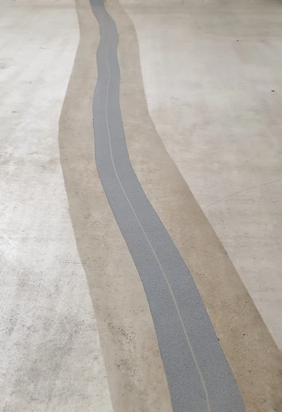
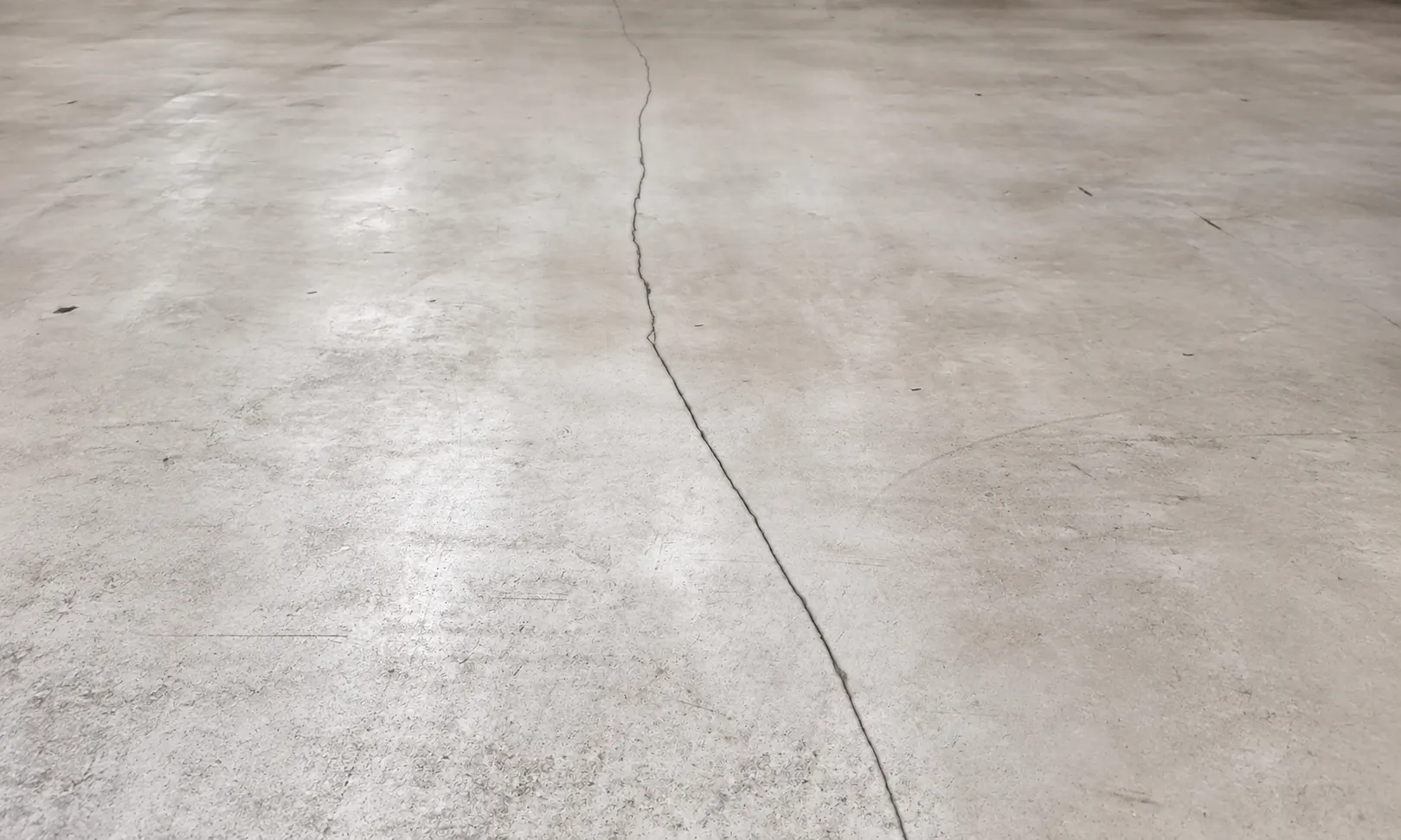
Industry | Logistics | Commercial · Stabilize lanes · Secure transitions · Clear clearance logic
Types and Methods of Crack Repair
Epoxy Resin Crack Injection (Bonded Crack Repair)
| Operating Principle | Low-viscosity epoxy resin is injected into the crack via packers and bonds the crack flanks together through mechanical interlock. |
| Delimitation | Suitable for dry, Cracks that are largely inactive; for active cracks, rigid bonding is not effective. |
| Typical industrial applications | Cracks in slab panels and edge zones that affect load-bearing capacity, with no significant crack movement. |
| Parameters (relevant to decision-making) | Industry-specific field | Interpretive Reference |
|---|---|---|
| Crack width (injection) | approx. 0.1-3.0 mm | Injectability / Material Selection |
| Fracture activity | Sedentary / Low physical activity | Suitability for adhesive bonding by friction |
| Moisture in the Crack | dry to slightly damp | Affects liability/litigation stability |
| Injection depth | continuous crack / through the entire thickness of the plate | determines the packer spacing and the amount of resin |
| Traffic Load | moderate to high (after stabilization) | Add edge/transition protection if necessary |
| Blocking time (typical) | 8-24 hours | Schedule Section Release |
Near-Surface Crack Filling (Milling/Opening and Filling with Epoxy Resin)
| Operating Principle | A crack is created close to the surface (groove), Cleaned and filled with resin or resin mortar; the goal is to ensure a smooth ride and reduce the ingress of dirt and moisture. |
| Delimitation | It primarily provides a functional surface treatment; it does not replace a deep-penetrating bonding system for structurally critical cracks. |
| Typical industrial applications | Lanes, Walking routes, Areas subject to recurring contamination and cleaning. |
| Parameters (relevant to decision-making) | Industry-specific field | Interpretive Reference |
|---|---|---|
| Crack width (visible) | approx. 5-10 mm | Groove Geometry and Material Selection |
| Groove width/depth | approx. 6-20 mm / 10-30 mm | Ride Comfort and Durability |
| Material System | EP / PU / AC (depending on function) | controls hardness vs. elasticity |
| Edge requirement | high on wheel load lines | Set Edge Profile/Radius |
| Cleaning Profile | dry/wet/chemical | Choose the Right Surface Finish |
| Blocking time (typical) | 2-24 hours | depending on the system and climate |
Polyurethane Crack Injection (flexible or moisture-tolerant crack sealing)
| Operating Principle | PU systems are injected into the crack, to achieve a sealed and/or more flexible connection (depending on the system). |
| Delimitation | Compared to EP, it is less focused on rigid bonding; suitable, when humidity or limited movement is a factor. |
| Typical industrial applications | Cracks Caused by Moisture Penetration, Areas near cracks with varying operating conditions, Areas with increased waterproofing requirements. |
| Parameters (relevant to decision-making) | Industry-specific field | Interpretive Reference |
|---|---|---|
| Crack width | approx. 0.5-5.0 mm | Sealing Effect / Injection Strategy |
| Fracture activity | low to moderate physical activity | Elastic compensation (system-dependent) |
| Moisture in the Crack | damp to wet | Process Selection and System Tolerance |
| Tightness Target | Dust- and liquid-resistant to watertight | Determines the PU system type |
| Traffic Load | low to medium (without edge reinforcement) | Secure wheel load zones separately |
| Blocking time (typical) | 2-12 hours | Suitable for short operating windows |
Crack Repair in Areas Near Joints and Transitions (Crack-Joint Interaction)
| Operating Principle | Cracks, on the sides of the joints, End at transitions or border areas, are treated as a combined damage mechanism: Stabilize the flank, Repairing Cracks: Functional and Structural Remediation, Smooth out the transition geometrically. |
| Delimitation | Simply filling cracks without repairing the flanks often leads to renewed spalling at the transition edge along wheel load lines. |
| Typical industrial applications | Tire Tracks Across Joints, Transitions Between Zones, Ramp and gate areas. |
| Parameters (relevant to decision-making) | Industry-specific field | Interpretive Reference |
|---|---|---|
| Location of the Crossing | directly at the joint/installation site | decides on a combination of measures |
| Side damage | intact to broken out | Prioritize flank rehabilitation |
| Fracture activity | often related to movement | System Selection (EP vs. PU) |
| Pass-through frequency | high | Check Edge/Profile Protection |
| Supplementary Joint Filling | semi-rigid / elastic | depending on the proportion of movement |
| Blocking time (typical) | can be planned by zone | Section Release Based on Traffic Logic |
Crack-bridging coating (elastic modification as a surface function)
| Typical industrial applications | Areas with a dense network of fine cracks, Areas Subject to Dynamic Loads, Areas with functional requirements (e.g., a defined interface). |
| Delimitation | No measure to restore a durable crack bond; suitable as a functional surface for microdefects associated with movement. |
| Operating Principle | A crack-bridging system layer (typically PU-based) absorbs micro-movements and reduces “marking” on the surface. |
| Parameters (relevant to decision-making) | Industry-specific field | Interpretive Reference |
|---|---|---|
| Type of crack | fine / mesh-like / micro | defines system logic |
| Level of physical activity | low to moderate | A crack-bridging design is advisable |
| System Thickness | approx. 1.5-4.0 mm | Power Reserve / Wear and Tear |
| Surface character | smooth to textured | Traction vs. Cleanability |
| Traffic Profile | medium (zoned) | Amplify hotspots separately if necessary |
| Blocking time (typical) | 12-48 hours | Access by Usage Level |
Crack Pinning (Stapling/Stitching) with Resin-Bonded Backing
| Operating Principle | Slots are cut perpendicular to the direction of the crack, and “pinning elements” are inserted, Redirect the loads across the crack; then seal it with resin mortar. |
| Delimitation | Mechanical reinforcement rather than simple sealing; recommended for cracks that require load redistribution, especially when crossing repeatedly. |
| Typical industrial applications | Cracks in high-traffic areas subject to bicycle traffic, when edge joints and crack openings are relevant to operations. |
| Parameters (relevant to decision-making) | Industry-specific field | Interpretive Reference |
|---|---|---|
| Crack width | approx. 0.5-10 mm | Geometry of Needling |
| Traffic/Load Level | moderate to very high | Rationale for Mechanical Reinforcement |
| Installation spacing (typical) | approx. 300-800 mm | Load redistribution along the fault |
| Installation depth | approx. 30-80 mm | depending on stock/sheet thickness |
| Supplementary Edge Profiling | often required | Reduce shock loads |
| Blocking time (typical) | 6-24 hours | Zonal implementation is possible |
Partial Replacement / Hotspot Replacement (Cutting Out and Rebuilding with Resin Mortar)
| Operating Principle | If the crack zones have already been crushed, are eroded or broken off, The affected area is carefully removed and rebuilt using resin mortar; the goal is to create a load-bearing zone with stable geometry. |
| Delimitation | Will be selected, When simple backfilling or grouting is no longer sufficient to stabilize the perimeter zone; the focus is on structural restoration. |
| Typical industrial applications | Areas Prone to Breakouts at Crack Intersections, Goal Lines, Intersections, Areas that have undergone repeated repairs. |
| Parameters (relevant to decision-making) | Industry-specific field | Interpretive Reference |
|---|---|---|
| Damage Area Size | local to several square meters | Define the intervention limit |
| Installation Height | typically 20-100 mm (locally) | Flatness/Ride Level |
| System Material | EP or AC/MMA mortar | Release Time vs. Robustness |
| Edge Profile | Radius/Bevel Defined | Reduce impact energy |
| Connection to Existing Infrastructure | form-fit/force-fit | Prevent Delamination |
| Release (typical) | 1-2 hours (AC/MMA) / 8-24 hours (EP) | Time Window Logic |
Crack Repair
Crack repair in industrial, logistics, and commercial facilities is a maintenance task for existing structures in which cracks are either stabilized using force-fit methods (such as needle-punching or bonding) or treated functionally (e.g., to seal or bridge cracks). Key factors include crack activity (static/dynamic), crack geometry (width/depth/path), traffic and point load levels, as well as contamination from cleaning or media. In areas subject to wheel loads, the design of edges and transitions determines whether the area remains permanently passable.
Quantec Industrieböden® GmbH performs crack repairs using systems based on epoxy resin, acrylic resin (MMA), and polyurethane, and typically structures the implementation according to zone and closure period logic.
Quantec Industrieböden® GmbH performs crack repairs using systems based on epoxy resin, acrylic resin (MMA), and polyurethane, and typically structures the implementation according to zone and closure period logic.

FAQ


Logistics, High-Bay Storage, Material Handling
Manufacturing, Mechanical Engineering, Material Handling
Food, Cold Storage, Clean Room
Chemistry, WHG, Media Contact
Request Crack Repair Services—With a Clear Method and Predictable Approval Process
Please send us the location, description of the damage, and your preferred time frame. You will receive a detailed assessment of how the crack can be professionally repaired.
The content of this page is intended to provide general information about Crack Repair and does not constitute project-specific technical planning or a guarantee of specific properties. Since specific requirements and results depend on individual on-site conditions, no liability is assumed for the accuracy of this information.


INDUSTRIEBÖDEN ® GmbH

Your symptoms
The Quantec Solution
We will be happy to contact you.
Would you like a personal telephone consultation?