


You are here:
Installing Inductive Loops - Reliable Vehicle Detection at Gates, Driveways, and in Aisleways
Quantec Industrieböden® GmbH handles the installation of induction loops in existing industrial, logistics, and commercial facilities—including precise slot cutting, professional casting, and coordinated installation while operations continue.
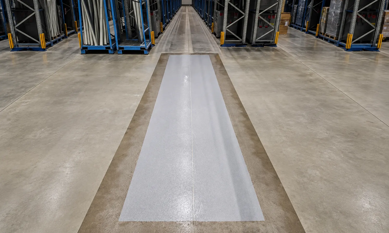
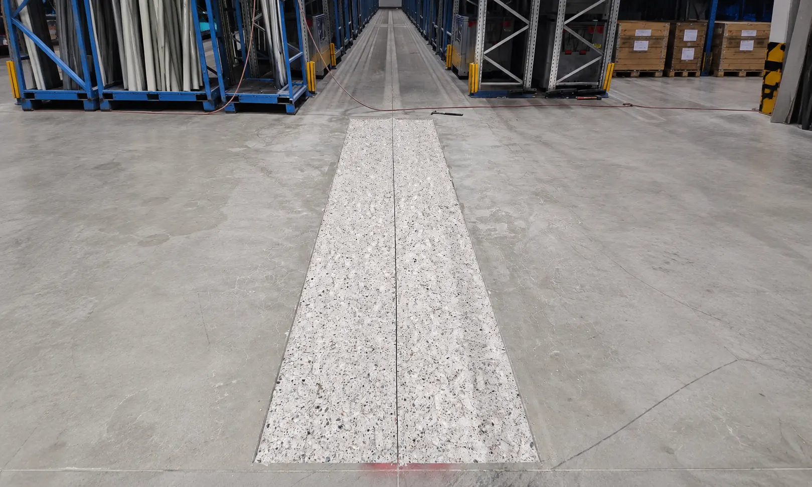
Induction loops are used for vehicle detection and typically control gates, barriers, or access processes. Correct geometry, clean slot alignment, and a robust encapsulation that withstands daily traffic and cleaning are crucial for reliability. Quantec integrates the retrofit in such a way that transitions remain stable and downtime can be planned.
Why Quantec?
Your Partner for Durable Industrial Floor Renovation
We don’t see ourselves as merely a service provider, but as a reliable partner at your side. Every renovation is planned carefully and precisely, carried out using high-quality materials, and designed for long-term use. This results in cost-effective and durable solutions for your industrial floor.

Clean slot + sturdy encapsulation
For a durable, stable surface in high-traffic areas.
Retrofitting Existing Buildings
Integration into existing lanes and crossings.
Scheduled Closure Times
Implementation in phases at access roads and gate areas.
100% in-house work
Our own machinery—no subcontractors.
Why Induction loops in the Floor Often Fail
Malfunctions are rarely caused by the loop itself, but rather by the installation conditions: Slots tear at the edges, the encapsulant is damaged by traffic and cleaning, or the location chosen is unsuitable for operation. In gate and access areas, this leads to unnecessary downtime, malfunctions, and increased maintenance costs.
Typical symptoms
Typical symptoms
- Cracks along the edges of slots in traffic lanes
- damaged concrete due to rolling loads and impact stress
- Recurring repairs in the gate area
- Unclear position of the loop in relation to traffic flow
- Frequent malfunctions in logistics access roads

Installation of Induction Loops as a Floor and Traffic Detail
Quantec treats induction loops as a functionally critical detail in the floor: The slots are cut in such a way that the edges remain stable, the grouting is tailored to the intended use, and the joints do not become new weak points. The goal is a surface that can withstand continuous traffic and functions reliably.
Services Related to Induction Loops
Planning and Installation Logic
- Alignment of the loop position (gates, barriers, access routes)
- Zoning based on traffic flow and closure time windows
- Implementation designed to ensure that operations and safety remain predictable
Slot Formation and Encapsulation
- Clean slot alignment and stable slot edges in the existing structure
- Proper grouting as a load-bearing surface feature
- Creation of a surface that can be driven over and is easy to clean
Interfaces with Remediation and Protective Measures
- Combination with jointand spot repair if the door area is already damaged
- Integration into crack repair if crack edges affect the slot zone
- Reliable joint bridging when the loop route crosses existing structural or expansion joints
What Factors Ensure Long-Term Operation
In practice, installation quality and protection against mechanical stress are what matter. Induction loops are often located in areas subject to high-frequency vibrations and shock loads.
Relevant Parameters (Selection)
Location
Gate area, barrier, access route, aisles in the high-bay warehouse, truck/forklift traffic
Frequency
Accident Frequency and Traffic Volume
Ground state
Breakouts, weak edges, cracks
Slot Geometry
Clean lines, sharp edges, transitions
Encapsulation Requirement
Abrasion, cleaning, contact with media (e.g., water/dirt)
Time window
Blocked Hours, Section Release, Off-Peak Hours
Installation at gates and driveways—with programmable access restriction times
Access roads are usually highly critical. Therefore, the implementation is planned so that road closures are kept to a minimum and detours are clearly defined.
Components of the Implementation
Components of the Implementation
- Segmentation by Access Routes and Gates
- Work during off-peak hours when traffic is heavy
- Designated crossings/temporary arrangements when detours are necessary
- Section-by-section clearance for rapid return to service

Typical Applications for Induction Loops
Warehouse doors with forklift or truck traffic
Barrier Systems at Plant Entrances
Access and Vehicle Access Control Systems in Logistics Centers
Retrofitting for new traffic routing or gate modifications
Replacement when existing loops are mechanically damaged
4 Steps to a Reliable Induction Loop
Belt Check
They specify the gate or barrier, the type of traffic, and any current maintenance or new construction requests.
Set the location and closing time
The loop configuration and section logic are adapted to the operation.
Installation: Slot + Encapsulation
Precise slot fabrication and durable encapsulation in existing structures.
Approval
Controlled access to the driveway or gate area.
Before
Afterward
Gates & Barriers · Vehicle Detection · Slotted Casting · Traffic Areas · Programmable Release
Types and Variants of Induction Loop Installation
Installation of Induction Loops in Asphalt (Existing Surface) with a Saw-Cut Groove and Epoxy Resin Encapsulation
| Delimitation | Outdoor areas are more susceptible to water, Subject to frost, thaw, and dirt; as a result, the casting and edge geometry are more critical than on interior surfaces. |
| Typical industrial applications | Driveways to Farms, Outdoor Barriers, Shunting Axles, Goal areas |
| Operating Principle | A groove is cut into the asphalt, Loop inserted, Then sealed; the goal is to secure the material and protect it against shear forces and moisture penetration. |
| Parameters (relevant to decision-making) | Industry-specific field | Interpretive Reference |
|---|---|---|
| Groove width | 5-8 mm | sufficient casting cross-section |
| Groove depth | 30-40 mm (common) / up to 70 mm (depending on the instructions) | Mechanical protection, coverage |
| Head | insulated copper wire (e.g., 1.5 mm²) | Mechanical Durability/Installability |
| Groove Cleaning | dust-free, dry | Adhesion and Leak-Tightness of the Encapsulation |
| Casting material | Epoxy resin/encapsulant (depending on the system) | Securing, Protection, Sealing Path Inspection |
| External stress | Water/Dirt/Temperature Changes | Impact on Detailed and Transition Training |
Installation of Induction Loops in concrete/industrial surfaces (existing) with a deep groove and flush-mounted cover
| Operating Principle | A groove is cut into concrete or hard existing surfaces, Loop inserted, then sealed and closed flush, to avoid sharp edges. |
| Delimitation | In high-traffic interior aisles, impact and shear forces dominate (forklift turns, Intersections); ensuring that the surface is restored to a flush finish is a key factor in the decision. |
| Typical industrial applications | Internal Access Roads, Industrial Doors, Controlled Lanes in Logistics |
| Parameters (relevant to decision-making) | Industry-specific field | Interpretive Reference |
|---|---|---|
| Groove Geometry | 5-8 mm wide, 40-70 mm deep | Cable/Encapsulation Protection in Drive-Over Zones |
| Corner Training | rounded/beveled | Protection of the conductor insulation |
| Securing the Ladder | completely at the bottom of the groove | Prevents movement within the slot |
| Surface flushness | 0-2 mm (target) | Minimizing Impact Force and Edge Wear |
| Casting/Final Position | low-porosity, mechanically robust | Durability Under Wheel Load |
| Section Approval | zoned | Integration into operating windows (e.g., night/weekend) |
Installation of Induction Loops: Prefabricated Loops vs. Custom-Made Loops (On-Site Assembly)
| Operating Principle | Pre-made loops are ready-to-use sets; custom-made loops are fabricated on-site from wire according to the target inductance and geometry. |
| Delimitation | Pre-assembled loops reduce installation variability; on-site assembly allows for adaptation to special geometries and groove configurations, However, it requires an inductance/resistance test. |
| Typical industrial applications | Standard Approaches (Pre-programmed Loop), Special Cases (Geometry, several turns, (special track widths). |
| Parameters (relevant to decision-making) | Industry-specific field | Interpretive Reference |
|---|---|---|
| Type of Garment | ready / on site | Adaptability vs. Standardization |
| Number of turns | typ. 3-5 | Inductance within the target range |
| Target Inductance | approx. 0.1-0.5 mH | Detector Compatibility |
| Feedline Drill | ≥ approx. 20 revolutions/m | Immunity to Interference/Signal Quality |
| Supply line length | Plant-specific; keep it brief | Attenuation/Susceptibility to Interference (Practical Driver) |
Installation of Induction Loops with shielded cables (slotted cable + shielded conduit/empty conduit) to the control cabinet
| Operating Principle | The loop is located within the driving surface; the supply cable is routed through a separate groove or through a conduit or protective channel, to reduce mechanical damage and interference. |
| Delimitation | Compared to a “through-slot” design, it is easier to maintain and more resistant to damage caused by subsequent work, However, this requires a clear separation of the cable routes. |
| Typical industrial applications | Systems with long pipeline runs, Outdoor Areas, Routine Maintenance |
| Parameters (relevant to decision-making) | Industry-specific field | Interpretive Reference |
|---|---|---|
| Route of the line | separated, with few intersections | Reduction of Interference Coupling |
| Distance from Other Cables | ≥ 10 cm | Minimize EMC/Induction Effects ( |
| Feedline Drill | ≥ 20 revolutions/m | Improve Immunity to Interference |
| Groove-to-Pipe Transition | sealed, mechanically protected | Input Path Check/Prevention of Runaway |
| Paving in the driving area | Epoxy/reaction resin (depending on the system) | Securing and Protection |
Installation of Induction Loops for Presence Detection at Barriers and Gates (Single Loop)
| Operating Principle | A rectangular loop generates a magnetic field; the presence of a vehicle alters the inductance, which is interpreted by the detector as a presence signal. |
| Delimitation | Compared to directional/dual-loop solutions, the single loop primarily provides a “vehicle present” signal in a defined field. |
| Typical industrial applications | Access Roads to Factory Premises, Barrier Systems, High-Speed Doors, Driveways to Farms |
| Parameters (relevant to decision-making) | Industry-specific field | Interpretive Reference |
|---|---|---|
| Loop Shape | Rectangle / Square | Field Shape and Detection Zone |
| Grain size | approx. 0.6 × 1.5 m to 2.0 × 2.0 m | Adjustment to Lane Width and Detection Target |
| Number of turns | typ. 3-5 | Target Inductance/Sensitivity |
| Target Inductance | approx. 0.1-0.5 mH | Detector Compatibility/Operating Range |
| Groove width | 5-8 mm | Cable protection and space for potting |
| Groove depth | approx. 40-70 mm | Covering over the conductor, mechanical protection |
| Corner Training | No sharp 90° corners | Reduction of Insulation Damage |
| Encapsulation | Epoxy resin/encapsulant (depending on the system) | Stability, Watertightness, Durability |
Installation of Induction Loops as Safety Loops in the Locking Area (Safety Loop)
| Operating Principle | The loop is located in the danger zone (e.g., under the barrier arm or the closing edge of the gate) and prevents the closing process from completing, as long as a vehicle is detected. |
| Delimitation | The detection field is designed to be narrower and zone-oriented; priority is given to stable presence detection at low speeds or when stationary. |
| Typical industrial applications | Barrier Systems, High-Speed Doors, Access Controls with Security Requirements |
| Parameters (relevant to decision-making) | Industry-specific field | Interpretive Reference |
|---|---|---|
| Grinding Position | directly in the lockout/hazard zone | Safety feature |
| Field coverage | "Stop-and-go" optimized | Stable detection at rest |
| Number of turns | typ. 3-5 | Sensitivity to slow-moving or stationary vehicles |
| Casting Quality | low-porosity, full-surface | Prevents the conductor from moving within the slot |
| Groove must be dry and free of dust | mandatory | Adhesion/Seal Integrity |
| Overlap over a conductor | ≥ approx. 25 mm (standard practice) | Protection Against Overload |
Installation of Induction Loops for Counting and Triggering (Counting / Trigger Loop)
| Typical industrial applications | Factory Traffic Count, Gate Logic, Lane Triggers at Bottlenecks |
| Operating Principle | Loops are placed as follows, that vehicles trigger defined events when they pass over them (counting pulse, Start of the test section, Trigger for gate/traffic light control). |
| Delimitation | Compared to the safety/presence loop, the focus is on reproducible pulse detection when the object passes through; standstill detection is secondary. |
| Parameters (relevant to decision-making) | Industry-specific field | Interpretive Reference |
|---|---|---|
| Grinding Position | Trigger Point in the Lane | Signal Timing Defined |
| Loop Length | 1.0-2.5 m (typical) | Pulse Duration vs. Speed |
| Detector Settings | Sensitivity/Filter | Resilience to Interference |
| Loop Resistance/Inductance | in the detector area | Prevents false alarms caused by misalignment |
| Cable Routing | twisted, not rolled up | Reduces coupling/false triggers |
Installation of Induction Loops in a Dual-Loop Configuration for Direction Detection
| Operating Principle | Two loops are arranged one behind the other at a defined distance; the detector determines the direction of travel based on the chronological sequence of the detection pulses. |
| Delimitation | Requires more effort to install than a single loop; in return, it provides additional information (direction/sequence), relevant to one-way logic, Access control or counting points. |
| Typical industrial applications | Separation of entry and exit lanes, Separate access logic, Traffic Management at Logistics Hubs |
| Parameters (relevant to decision-making) | Industry-specific field | Interpretive Reference |
|---|---|---|
| Number of loops | 2 | Directional analysis possible |
| Loop Spacing | approx. 1.0-3.0 m | Depending on speed and the evaluation window |
| Geometric Synchronization | equal/adjusted | Comparability of the Signals |
| Freedom of Intersection of Lines | no crossover | Avoid Interference |
| Minimum clearance from other cables | ≥ 10 cm | Reduction of Electromagnetic Coupling |
| Cable Routing | twisted to the detector | Immunity to Interference/Signal Quality |
| Groove Geometry | 5-8 mm / 40-70 mm | mechanical protection, such as a single loop |
Installation of Induction Loops
The installation of induction loops is an electromechanical retrofit in existing traffic and access areas, in which a wire loop is embedded in the pavement as a sensor and connected to a loop detector. The key technical factors here are loop geometry, number of turns, cable routing (twisted-pair cable), groove geometry, and the encapsulation, as these parameters determine detection stability and durability in traffic zones. In industry and logistics, the focus is typically on barrier/gate control, access and presence detection, and secure restricted areas. Quantec Industrieböden® GmbH performs the installation as a retrofit and seals grooves with systems based on epoxy resin, acrylic resin, and polyurethane, without the need to rebuild concrete or screed structures or lay asphalt or PVC.

FAQ


Logistics & Warehousing
Mechanical Engineering & Manufacturing
Food & Hygiene
Cold Storage & Temperature Fluctuations
ESD & Special-Purpose Functional Surfaces
Chemistry/Media & WHG/AwSV
Outdoor Areas & Traffic Areas
Parking & Access/Traffic Control
Installing Induction Loops—Durable, Drive-Over, and Customizable
Please send us the location, mode of transportation, and time window. You will receive a structured assessment of how this can be implemented in your existing operations.
The content of this page is intended to provide general information about Installation of Induction Loops and does not constitute project-specific technical planning or a guarantee of specific properties. Since specific requirements and results depend on individual on-site conditions, no liability is assumed for the accuracy of this information.


INDUSTRIEBÖDEN ® GmbH

Your symptoms
The Quantec Solution
We will be happy to contact you.
Would you like a personal telephone consultation?