


You are here:
Renovating Swap Body Parking Spaces - Safely Handling Peak Loads
Quantec Industrieböden® GmbH renovates parking spaces for swap bodies in logistics and transshipment areas—with a focus on permanently stable surfaces, durable transitions, and predictable approvals during ongoing operations.
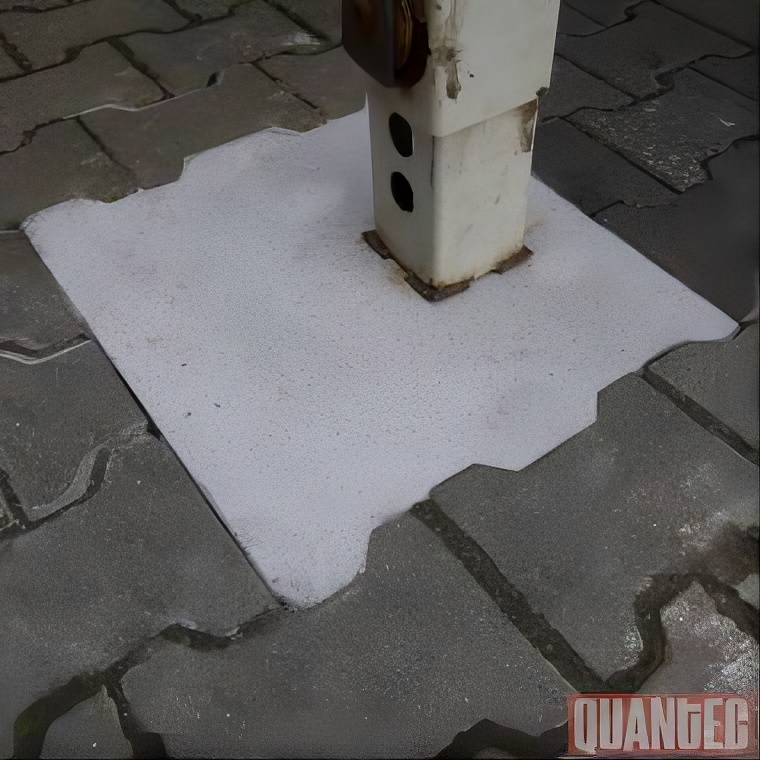
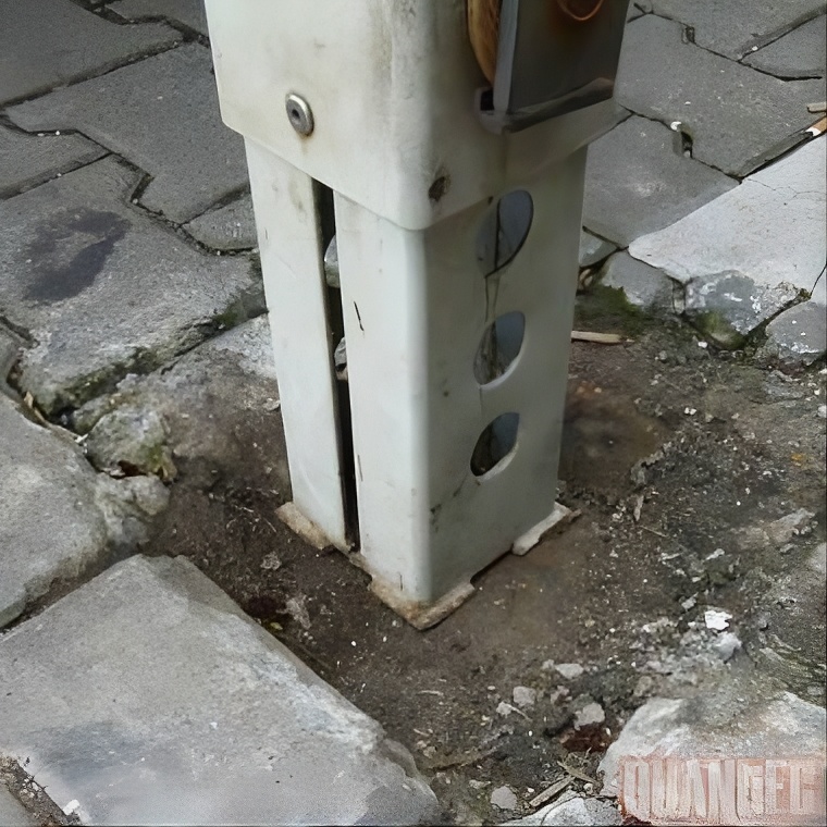
Swap body parking areas are typical hotspots: recurring point loads, maneuvering, and impact stresses concentrate damage in just a few areas. As spalling, edge chipping, or cracks increase, safety risks and downtime rise. A technically sound, zone-based repair stabilizes the contact areas and reduces secondary damage in traffic lanes and transition zones.
Why Quantec?
Your Partner for Durable Industrial Floor Renovation
We don’t see ourselves as merely a service provider, but as a reliable partner at your side. Every renovation is carefully and precisely planned, carried out using high-quality materials, and designed for long-term use. This results in cost-effective and durable solutions for your industrial floor.

Expertise in Point Loads and Hotspots
Upgrades to address recurring peak loads in cargo-handling areas.
Phased Release
Implementation based on traffic logic—suitable for ongoing operations.
Durable Materials
Materials with high point loads (up to 70 N/mm2)
In-house production using our own machinery
End-to-end execution without subcontractors.
Why Swap Body Parking Spaces Can Quickly Become a Problem
Parking spaces for swap bodies are subject to high stresses: Contact surfaces are repeatedly subjected to localized loads, maneuvering generates shear forces, and crossings into adjacent traffic lanes introduce impact loads. Without stable edge zones and robust transitions, spalling, cracks, and permanently “unstable” crossings occur.
Typical damage patterns at the parking space
Typical damage patterns at the parking space
- Spalling and flaking in the contact surfaces
- Edge spalling at transitions, particularly to the traffic lane
- Cracks and crack networks caused by repeated load cycles
- Height differences and impact stress at crossings
- Damage to joint areas with progressive destruction of the edge zones

Parking Space Renovation as a Zoned Approach Rather Than Individual Repairs
Quantec renovates swap body parking areas with clear zoning: load-bearing surfaces are stabilized, transition areas are mechanically protected, and adjacent traffic areas are integrated in such a way that no “soft” interfaces are created. The goal is a durable, load-bearing usable area with a predictable approval timeline.
Services for Swap Body Parking Spaces
Stabilization of the contact surfaces
- Repair of areas subject to point loads using appropriate repair systems
- Restoration of load-bearing edge zones in the parking area
- Integration with adjacent areas to reduce secondary damage
Transitions, Edges, Mechanical Protection
- Protection of critical edges and transitions where maneuvering loads “take effect”
- Installation of heavy-duty profiles at transitions (as needed)
- Renovation of crossings with defined passability
Interfaces: Joints, Cracks, Coatings
- Repairingexpansion joints in parking lot areas to stabilize the perimeter zones
- Crack repair in parking spaces and traffic lanes
- EP/AC/PU-basedcoatings for surface stabilization, depending on usage
Which Factors Determine the Renovation
A swap body parking space is not a “normal warehouse floor.” The key factors are the combination of point loads, maneuvering movements, and transition geometry.
Relevant Factors
Load Profile
Contact surfaces, recurring load peaks, maneuvering movements
Traffic Management
Forklift routes, gate/ramp areas, crossings
Damage Mechanics
Spalls, Cracks, Edge Weakness, Height Discrepancy
Stability
Subgrade Structure / Bearing Capacity / Support Geometry
Surface Requirements
Abrasion, traction, optional marking/path guidance
Renovation with minimal disruption to cargo handling operations
Logistics facilities must remain operational. Parking spaces can often be planned in such a way that operations continue in a controlled manner while individual zones are repaired one after another.
Typical Approach in Practice
Typical Approach in Practice
- Zoning by parking space rows and traffic routes
- Authorizations by section with clearly defined transitions
- Implementation within short time windows for critical parking spaces
- Construction site logistics tailored to workplace safety and maneuvering operations

Typical situations in which parking spaces are renovated
Recurring outbreaks at points of friction
"Progressive" damage along the driving lane caused by weakness in the edge zones
Impact Loads at Crossings with Increasing Height Differences
Damage to joints in the area surrounding the parking space
Need for rapid approval during periods of high workload
Durability is created at the junctions
Many repairs fail not because of the damaged area itself, but because of the transition to the existing surface. That is why parking space renovations are carried out in such a way that the edge zones and transitions are mechanically stable and loads do not cause the edges to “split open” again.
Quality Factors That Matter in Business Operations
Load-bearing contact surfaces without edge fractures
defined transitions to lanes and crossings
Effective combination with joint and crack repair
Choosing a System Based on Abrasion, Time Frame, and Usage
Parking Spot Check (Hotspots + Usage)
They provide information on damage patterns, usage, and time windows. The goal is to prioritize: which parking spaces to address first, and which walkways are critical.
Renovation Plan with Zoning
You will receive a design for contact surfaces, transitions, and connections—including approval for each section.
Do-It-Yourself Installation + Approval
The work is carried out using our own equipment, without subcontractors. Once the work is completed and approved, the parking spaces are once again ready for use and can be scheduled accordingly.
Before
Afterward
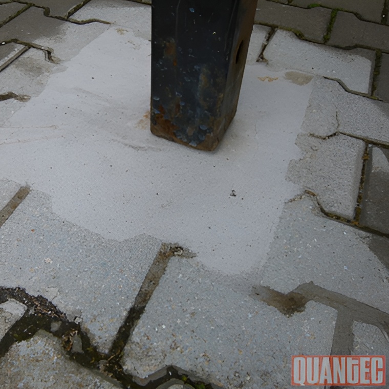
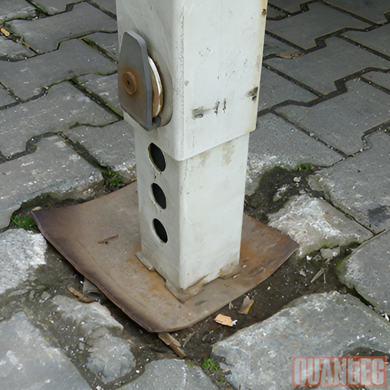
Logistics | Cargo Handling | Loading Areas · Stabilize Loading Surfaces · Protect Transitions · Predictable Clearance
Types and Varieties of Swap Body Parking Spaces
Outdoor Swap Body Parking Space with drainage and freeze-thaw loads
| Operating Principle | Detailed design focuses on controlled water drainage and robust edge zones, because standing moisture and temperature fluctuations place particular stress on the edges of pads, profiles, and joints. |
| Delimitation | Internal solutions without joint management often result in water infiltration, edge spalling, and recurring repairs at joints. |
| Typical industrial applications | On-site and Off-site Delivery, Parking spaces near gates and ramps |
| Design feature | Industry-specific field | Technical Significance | System/Detailed Approach |
|---|---|---|---|
| Slope/Drainage | approx. 1.0-2.5% | Prevents liquid from pooling on the pads | Design transitions so that water does not “pool” |
| Moisture/Freeze-Thaw Stress | high | Peripheral damage and infiltration | Tight seal, stable connection geometry |
| Additives | Sand/Salt/Dirt | Abrasion and Pore Blockage | Seal to minimize pores, smooth edges |
| Temperature Range for This Model | project-dependent | manages system selection and approval | AC(MMA) for short windows, EP/PU for longer ones |
| Connection to Asphalt/Concrete | critical | A change in material creates a vulnerability | defined transition phase, stable against shear |
| Maintenance access | required | Make Cleaning and Inspection Easier | Robust, serviceable components |
Swap Body Parking Spaces near media or WHG facilities (leakage/cleaning zones)
| Operating Principle | Installation sites in areas where contact with media is possible are designed using seal path checks and media-specific surface logic; entry paths at cracks, joints, and transitions are prioritized. |
| Delimitation | "Chemical-resistant" here refers to the type of medium and the exposure time, Areas subject to the Water Resources Act (WHG) require systematic training in suitability assessment and detailed training in accordance with the guidelines. |
| Typical industrial applications | Parking Spaces Near Maintenance Facilities, Cleaning Areas, Areas with recurring fluid inflow |
| Design feature | Industry-specific field | Technical Significance | System/Detailed Approach |
|---|---|---|---|
| Media Profile | company-specific | Choosing a Topcoat/Sealant | EP/PU/AC by Medium and Cleaning |
| Exposure time | short to upright | Risk of infiltration | Detailed information, close entry paths |
| Cleaning Chemicals | process-dependent | Surface Stability in Everyday Life | Top layer compatible with the cleaning regimen |
| Joints/Transitions | mission-critical | most common entry path | Joint/edge zone rehabilitation, defined connections |
| WHG Boundary Condition | project-dependent | Defines the scope of documentation and detail | System-compliant design in subzones |
| Repairability | required locally | Operation must not be blocked | Zonal repair instead of full-surface repair |
Row parking space (multiple parking spaces) with guidance, stopping, and safety zones
| Operating Principle | Parking spaces are arranged in a repeating grid pattern; defined zones for support feet, rear supports/stops, and maneuvering lines reduce misalignment and concentrate stress in areas designed for high durability. |
| Delimitation | Compared to individual parking spaces, the focus is on systematization (grid layout, repetitive geometry, load-based zoning). |
| Typical industrial applications | Freight yards, Transshipment terminals, Contract Logistics with High Storage Density |
| Design feature | Industry-specific field | Technical Significance | System/Detailed Approach |
|---|---|---|---|
| Grid Dimensions for Parking Space | company-specific | manages traffic flow and hotspots | Repeatable pad/plate positions |
| Position Tolerance (Practical) | to keep it small | reduces edge stress on the pad | Marking + robust support zone |
| Rear contact zone | frequently subjected to impact loads | Prevent Breakouts at the Point of Contact | Reinforced zone + profile (if applicable) |
| Shunting Line | very busy | Abrasion/Shear Concentrated | Bedding/top layer divided into zones, if necessary |
| Pedestrian Safety Zones | to plan separately | reduces conflicts with shunting | Marked as a secondary service |
| Maintenance Plan | modular repair | Keep Recurring Damage Localized | Replaceable/segmented reinforcement zones |
Rapid-Release Renovation of Swap Body Parking Spaces (AC/PMMA Design Variant)
| Operating Principle | Time-sensitive parking spaces are repaired in cycles; rapid curing allows for phased reopening, while the robust geometry of the pads and transitions is preserved. |
| Delimitation | This is a layout and system option, not a different type of parking space., The load mechanics remain the same; the release logic takes precedence. |
| Typical industrial applications | Night/Weekend Window, Rows of parking spaces without a permanent detour, Tornahe Bottlenecks |
| Design feature | Industry-specific field | Technical Significance | System/Detailed Approach |
|---|---|---|---|
| Time window | approx. 2-8 hours | Sets the beat length and time signature | AC(PMMA) mortar, fast-setting |
| Cycle Length per Section | Approx. 1-6 parking spaces | Traffic Management During Construction | Prioritization by Rows |
| Approval Levels | On Foot/Transport/Trailer | Controlled commissioning | Defined usage levels per cycle |
| Hotspot Share | local to high | Scope of the Preliminary Work | Cutting/Reprofiling Before Assembly |
| Transitional Training | Flush/beveled connection | immediate response to being run over | Geometry is critical for approval |
| Temperature/Ventilation Logic | relevant | Process stability | Link the process to environmental conditions |
Existing asphalt Swap Body Parking Space with load-distributing support islands
| Operating Principle | Create load-distributing islands on asphalt surfaces to limit rutting, shear waves, and local subsidence at support feet; transitions are designed so that no new joint edges are created. |
| Delimitation | Asphalt reacts differently to point loads and temperature; therefore, this measure focuses on load distribution and shear strength in the support area. |
| Typical industrial applications | Outdoor yards and switching yards, where the asphalt is not being repaved but the support points need to be stabilized. |
| Design feature | Industry-specific field | Technical Significance | System/Detailed Approach |
|---|---|---|---|
| Temperature/Summer Load Case | seasonally relevant | Affects the tendency of asphalt to deform | Islands with push-stable integration |
| Deformation/Ruts in the Support Area | local to pronounced | Factors Affecting Island Size and Peripheral Zone | a larger support pad instead of a “small pad” |
| Support Island Dimensions | approx. 0.4 × 0.4 m to 1.0 × 1.0 m | Distributes pressure, reduces indentation | EP/PU/AC mortar islands, depending on inventory |
| Transition: Island ↔ Asphalt | chamfered/flush | Prevents chipping at the edge | Defined bevel, low-porosity finish |
| Thrust Loads During Maneuvering | medium-high | Risk of Shearing at the Edge of the Island | Sufficient embedment depth, edge zone bearing capacity |
| Moisture/External Source | highly possible | Prevent Water Seepage and Frost Damage | Smooth surface finish, precise details |
Existing Swap Body Parking Space on a concrete slab with support zones reinforced for point loads
| Operating Principle | Local reinforcement of the support points (support feet/leveling feet) using high-strength reactive resin mortar zones and a defined geometry to reduce indentation, edge chipping, and microcracking in the contact surface. |
| Delimitation | In contrast to a uniform coating, the focus is on localized load distribution; the wear layer serves a secondary function in terms of surface performance. |
| Typical industrial applications | Parking spaces in buildings and on paved courtyards, provided the concrete surface is generally load-bearing but is cracking at the support points. |
| Design feature | Industry-specific field | Technical Significance | System/Detailed Approach |
|---|---|---|---|
| Temperature/Summer Load Case | seasonally relevant | Affects the tendency of asphalt to deform | Islands with push-stable integration |
| Deformation/Ruts in the Support Area | local to pronounced | Factors Affecting Island Size and Peripheral Zone | a larger support pad instead of a “small pad” |
| Support Island Dimensions | approx. 0.4 × 0.4 m to 1.0 × 1.0 m | Distributes pressure, reduces indentation | EP/PU/AC mortar islands, depending on inventory |
| Transition: Island ↔ Asphalt | chamfered/flush | Prevents chipping at the edge | Defined bevel, low-porosity finish |
| Thrust Loads During Maneuvering | medium-high | Risk of Shearing at the Edge of the Island | Sufficient embedment depth, edge zone bearing capacity |
| Moisture/External Source | highly possible | Prevent Water Seepage and Frost Damage | Smooth surface finish, precise details |
Swap Body Parking Spaces with heavy-duty edge protection profiles along the drive-through and maneuvering lanes
| Operating Principle | Steel profiles protect edges, transitions, and edge lines where forklifts or trailers repeatedly drive over or bump into them; the profile edge absorbs impact and shear stresses and stabilizes the connection area. |
| Delimitation | Unlike standard support pads, this version addresses the impact forces and edge damage along the shunting routes. |
| Typical industrial applications | Rows of parking spaces along the goal lines, Ramps, Intersections and bottlenecks with high traffic volume |
| Design feature | Industry-specific field | Technical Significance | System/Detailed Approach |
|---|---|---|---|
| Impact/Shear Component | high when changing direction | Key Drivers of Profile Demand | Heavy-duty profile + side-flange connection |
| Profile Thickness | approx. 6-15 mm | Wear and Shock Reserve | Cross-Section Based on Traffic Profile |
| Embedding depth | approx. 30-80 mm | Breakaway Protection in Existing Installations | EP/AC Mortar for Embedding |
| Edge Profile (Chamfer/Radius) | defined | reduces edge impulse | geometrically balanced connection |
| Passing Speed | low-medium | determines impact energy | Contouring the crossing zone |
| Connection to Existing Space | flat/low-porosity | reduces edge chipping and contamination | Fill the gap with putty |
Swap Body Parking Space with steel plate support points (parking plates)
| Operating Principle | Steel plates placed under the support feet create defined contact surfaces and distribute loads to the reinforced substructure; the plates prevent localized indentations at the contact points. |
| Delimitation | Unlike pads made entirely of mortar, the contact zone is defined by metal, which can reduce surface pressure and wear on the support foot. |
| Typical industrial applications | Parking spaces with varying types of swap bodies, frequent repositioning, and high point load dispersion. |
| Design feature | Industry-specific field | Technical Significance | System/Detailed Approach |
|---|---|---|---|
| Panel Dimensions | approx. 250×250 to 500×500 mm | Surface Compression and Propensity for Settlement | Steel plate embedded in a mortar bed |
| Sheet Thickness | approx. 10-25 mm | Deflection/Deformation Under Load | Design a cross-section for a load combination |
| Embedding depth | approx. 20-60 mm | Stability Against Skidding and Tipping | EP/AC mortar bed, form-fit |
| Surface flushness | 0-2 mm (target) | Ride Quality and Impact Impulse | Flush mounting, chamfered edges |
| Corrosive environment | dry to wet | Service Life of Panels/Connections | Steel with a protective coating or stainless steel |
| Maintainability | required | Replacement in Case of Damage | solution-oriented panel geometry |
Swap Body Parking Spaces
Swap body parking areas are high-stress logistics areas where swap bodies transfer loads to the ground at specific points via support feet and, if applicable, rear support points, and where additional shear and impact loads occur during repositioning. Typical applications include freight forwarding, contract logistics, production logistics, and transshipment centers—particularly in row parking areas, gate lines, and maneuvering aisles. Key factors in the design include support geometry, the risk of indentation or cracking, drive-over edges, and outdoor drainage systems. Quantec Industrieböden® GmbH handles the renovation of swap body parking bays in existing facilities using system solutions based on epoxy resin and acrylic resin (PMMA) mortars, as well as profiled edge protection solutions, including zoned implementation according to operational windows.

FAQ


Logistics & Warehousing
Manufacturing & Mechanical Engineering
Food & Hygiene
Cold Storage & Temperature Fluctuations
Chemistry/Media & WHG/AwSV
ESD & Special-Purpose Functional Surfaces
Renovating swap body parking spaces—with a predictable approval process
Please send us the key details: number of parking spaces, nature of the damage, and time frame. You will receive a structured assessment and a proposal for implementation.
The content of this page is intended to provide general information about Swap Body Parking Spaces and does not constitute project-specific technical planning or a guarantee of specific properties. Since specific requirements and results depend on individual on-site conditions, no liability is assumed for the accuracy of this information.


INDUSTRIEBÖDEN ® GmbH

Your symptoms
The Quantec Solution
We will be happy to contact you.
Would you like a personal telephone consultation?